

SECTION 3
Exploring Interference Mitigation Improvements
In investigating how these negative effects can be mitigated, we asked: how can we ensure that connected devices flying over an LTE network do not degrade the connectivity of the terrestrial devices? How can we ensure a consistent quality of service level for both drones and terrestrial devices?
Our study centered on investigating interference mitigation approaches both in the uplink and downlink, some that would require evolution of the LTE standard, and some that can be implemented now in a transparent manner in existing networks. We explored interference mitigation techniques for both the downlink (to protect aerial devices) and the uplink (to protect terrestrial devices).
To mitigate the downlink interference, we proposed a simple adaptation of the interference mechanisms already defined in the LTE standard. These include: 1) joint transmission coordinated multipoint (JT-COMP), a technique that combines the transmissions from two or more cells (see Figure 8(a), green arrows) so that they no longer act as interfering cells but rather improve the quality of the received signal; and 2) almost blank subframe (ABS), a coordination scheme between neighboring base stations whereby certain signals are muted (see Figure 8(b), white arrows representing blanked signals).
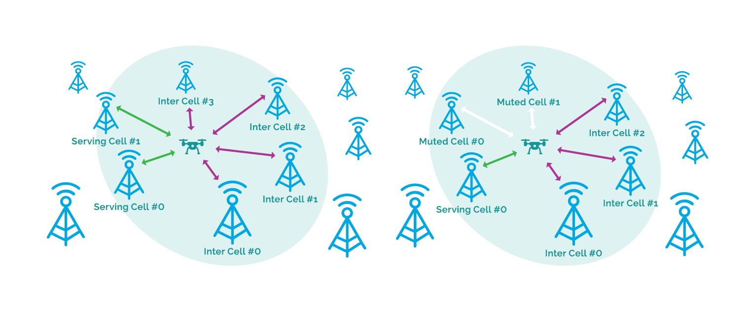
Figure 8: Drone downlink interference mitigation using (a) JT CoMP, and (b) ABS eICIC
Figure (a) on the left, and figure (b) on the right.
Both approaches rely on coordination between neighboring cells, which may not be trivial and will increase the traffic on the interface between the base stations (also known as the X2 interface). Furthermore, such solutions will not necessarily improve the uplink interference issue.
Another approach relies on using sectorized antennas, or beamforming antennas on the aerial device.
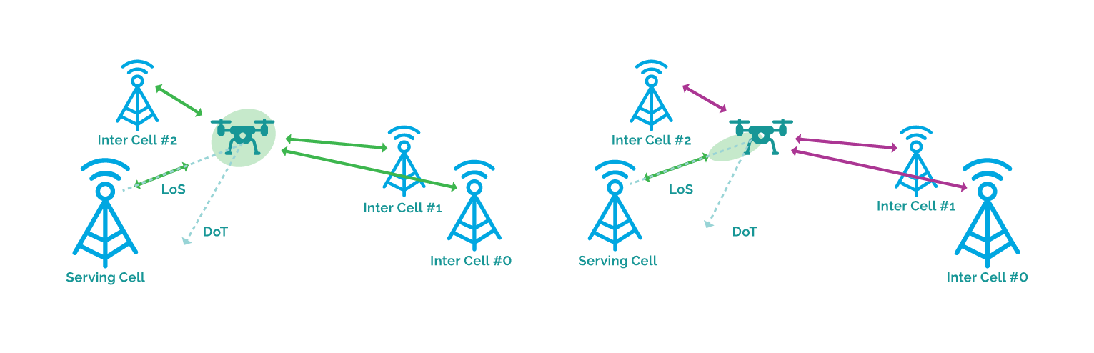
Figure 9: Drones with and without a steerable antenna
Figure (a) on the left without steerable antenna, and figure (b) on the right with steerable antenna.
For aerial UEs, the signal from the serving cell and inter-cells is very likely to arrive from line-of-site (LOS) cells. The use of omni-directional antennas allows interfering cells to pollute the serving cell’s downlink signal to the aerial, and the aerial to pollute the uplink signal to other (terrestrial and aerial) UEs of the network, as depicted in Figure 9 (a). Thus, the use of directional antennas can be extremely useful in suppressing the interference from a large number of inter-cells. The interference suppression is dependent on the used beam width and the direction of the broadside.
The ideal solution is to be able to track the serving cell dynamically with a steerable beam (either mechanically, or electronically) to ensure maximum gain for the desired signal and maximum nulling of interfering signals. This approach works equally well for uplink and downlink.
Figure 10 illustrates the gains possible with the use of antenna patterns of various beam widths. The narrower the beam, the better the performance. Beam width is usually defined by the angle for which the power is 3dB lower than the maximum power in the broadside of the antenna pattern.
Using a 15-degree beam width, almost all degradation seen by the aerials with omnidirectional antennas is recovered.
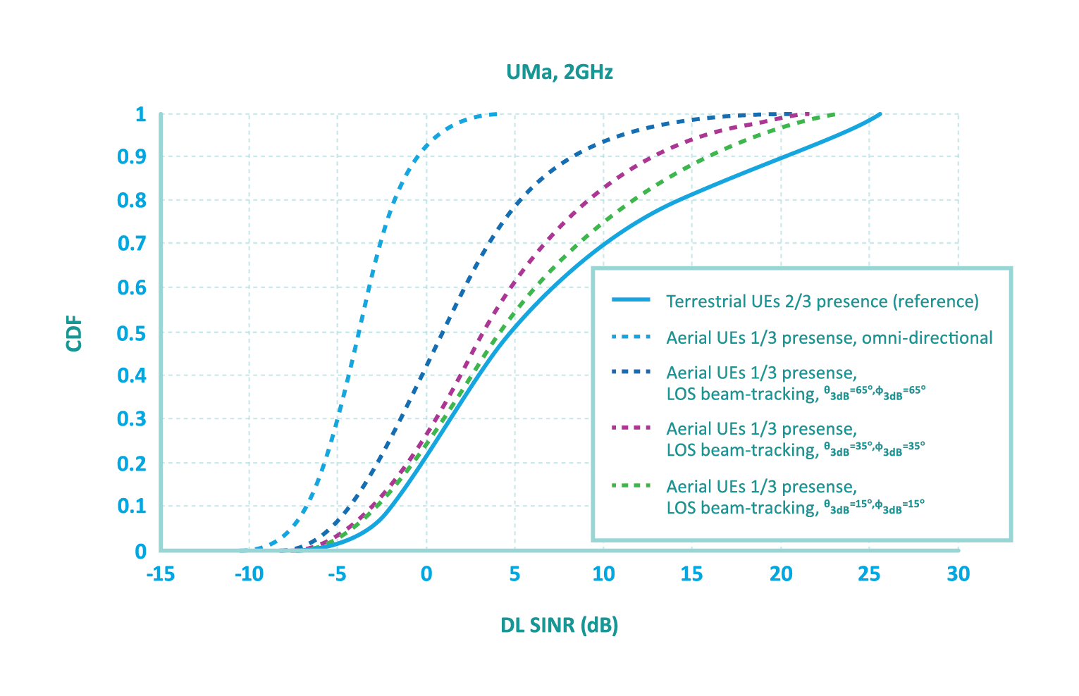
Figure 10: Downlink SINR CDF performance of aerials using beamforming and beam tracking
Shown with various beam-widths (dashed lines) compared to the downlink of terrestrial UEs (solid line).
Similarly, Figure 11 shows the improvement seen by the terrestrial UE on the uplink when the aerials use various antenna patterns. With a 15-degree beam, the uplink performance of the terrestrial UEs is no longer degraded by the presence of aerials.
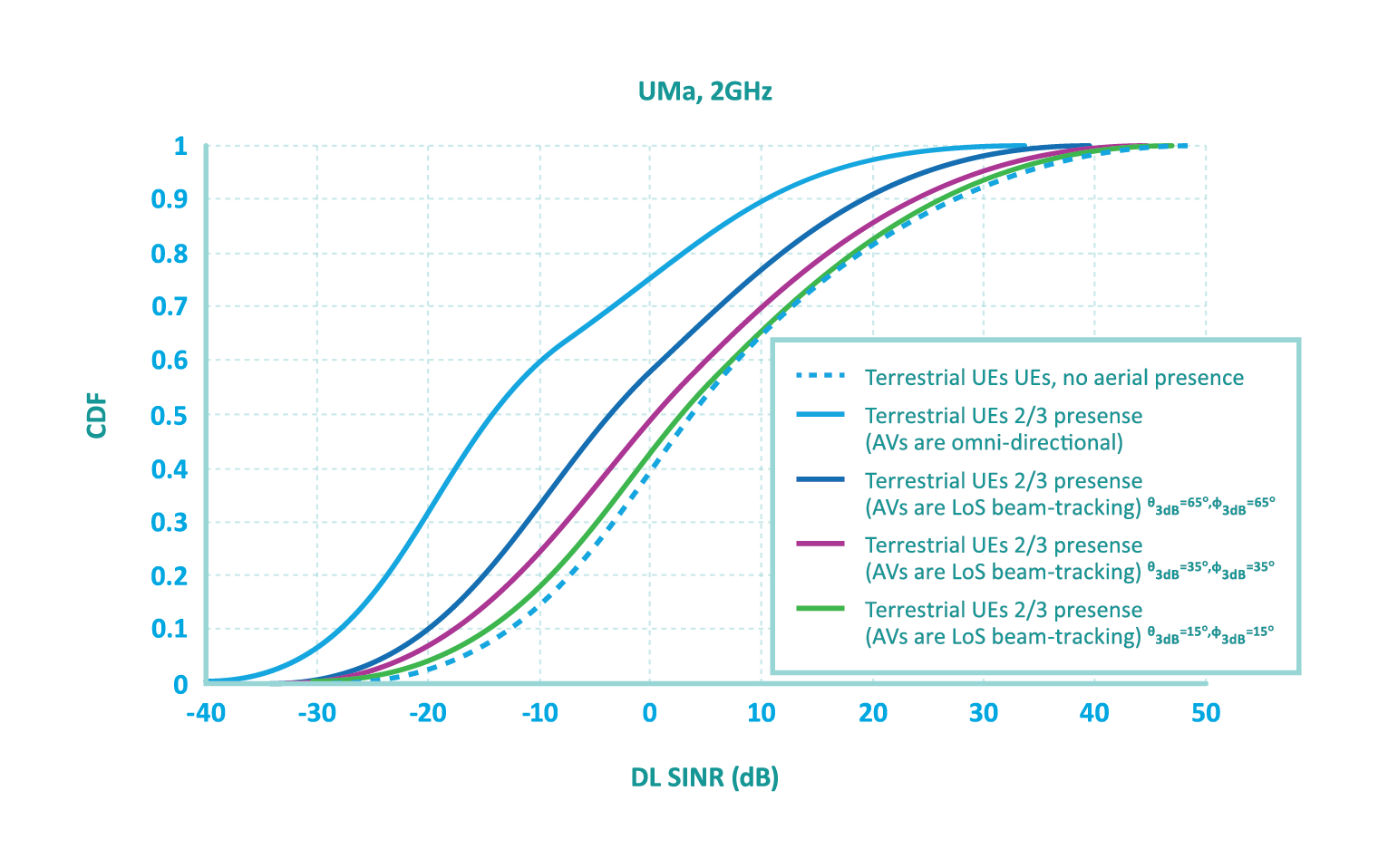
Figure 11: UL SINR CDF performance of terrestrial UEs in the presence of aerials using omni-directional antenna or beamforming (LOS tracking)
Shown with various beam widths (solid lines) compared to the uplink of terrestrial UEs without the presence of aerials (dashed line).
In practice, it may be difficult (and costly) to create an ideal narrow beam and maintain it in a given direction but simple approaches may be imagined and deployed on the aerial UE side. For instance, one can imagine a quadcopter drone with 4 90-degree beam width antennas, with one antenna per drone leg, and replacing the ideal beam tracking with a simple antenna switch. Overlapping antenna patterns could conceivably ease handover and avoid a possible ping-pong effect within the antenna switches. Such solutions are easily implementable on the device and would require simple customization of the UE’s modem firmware. The current discussion in the 3GPP may also extend to include aerials in the existing LTE feature that allows the network to control antenna switches on the UE.
Several methods can be put in place that would mitigate the interference generated by the aerials in the uplink and would provide better downlink SINR to the aerials. Some approaches rely on the network but could be complex to deploy in practice. Other approaches rely on simple adaptation of the aerial device.
In the end, it may be required to adapt the standard so the network can distinguish between aerial devices and terrestrial devices. The interference mitigation schemes briefly described above would then have to be put in place only when required, e.g., when the device is flying above the usual height. In addition, mechanisms such as location, speed and angle of arrival estimations may have to be updated to include the possibility of drones. All these topics were addressed in the early discussion in 3GPP and summarized in the technical report TR 36.7771. The actual standardization process began in December 2017 and is expected to be completed in June 2018.4
The 3GPP community is addressing the point and will provide technical recommendation within the Release 15 framework, by June 2018.
Test Your Knowledge
Participate in the quiz to test your knowledge throughout the white paper experience. Upon completing the quiz you will have a chance to provide your email address in order to receive an email summarizing your responses.
Thank you for participating. Enjoy!
